40M Mini-loop Antenna
By Rob L. Dey, KA2BEO 11/17/94
Thanks to Rod Newkirk, W9BRD in QST July 1993 p. 34-35 & 39
Also see QST November 1993 p. 37-40 & 84, and QST November 1994 p. 87
 PHOTO A
 PHOTO B
Specifications
SIZE: 4.5'W x 3.5'H x 0.5"D approx. (less than 1% the space of a dipole)
FEEDPOINT IMPEDANCE: Balanced, 50-ohms approx.
CENTER FREQUENCY: 7.14 MHz
SWR: 1.25:1
BANDWIDTH (2:1 SWR): 100 kHz, 7.09-7.19 MHz
POWER RATING: 150 W rms
TUNING: None required, pretuned design.
GROUND: None required, balanced design. Also, no balun required for coax feed.
MAINTAINANCE: None required, completely weatherproof.
MOUNTING: Hang vertically in any convenient location, even in the basement.
Feedpoint is at the top.
RADIATION PATTERN: Major lobes in front and back at all elevation angles.
Parts Required
4 1/2" CPVC 90° Elbow
1 1/2" CPVC Tee
2 1/2" CPVC Male Threaded Adapter
1 1/2" CPVC Slip Cap with 3/8" dia. hole drilled in end
16' 1/2" CPVC Tubing, cut into lengths of: 2 @ 41.250", 2 @ 24.000", 2 @
26.250", 1 @ 0.750"
16.5' 16/3 Power Cord/Cable 3 x 16 AWG, each wire stranded 26 x 30 AWG, type
SJTW-A 75°C
1 PVC Outlet "T" Box, 1-gang, rectangular with two 1/2" threaded holes
GAMPAK #13250
1 PVC Outlet Box Cover, 1-gang with gasket and four S/S mounting screws
GAMPAK #13240
1 BNC Female Connector with flat washer, locking solder lug, and nut
6 3/16"L #6-32 Machine Screw
6 #6 Locking Solder Lug
3 25pf ±10% 7.5kV NPO Doorknob Capacitor HEC #HT50 or equiv.
1 10pf ±5% 5.0kV NPO Ceramic Capacitor HEC #HT53 or equiv.
5pf ±0.5pf 5.0kV NPO Ceramic Capacitor HEC #HT55 or equiv. (optional)
CPVC Primer/Cleaner (Oatey)
CPVC Cement/Adhesive (Oatey)
Parameters
T = 3
l = 41.958m @ 7.15MHz
A = 4.0005m˛ (15.75ft˛)
Rr = 1.45-ohm
Rl = 0.839-ohm
n = 63% (-2dB)
Wd = 0.0508"od
Ws = 0.0625"
h = 1.8m (7ft)
Q = 71.5
PHOTO B
Specifications
SIZE: 4.5'W x 3.5'H x 0.5"D approx. (less than 1% the space of a dipole)
FEEDPOINT IMPEDANCE: Balanced, 50-ohms approx.
CENTER FREQUENCY: 7.14 MHz
SWR: 1.25:1
BANDWIDTH (2:1 SWR): 100 kHz, 7.09-7.19 MHz
POWER RATING: 150 W rms
TUNING: None required, pretuned design.
GROUND: None required, balanced design. Also, no balun required for coax feed.
MAINTAINANCE: None required, completely weatherproof.
MOUNTING: Hang vertically in any convenient location, even in the basement.
Feedpoint is at the top.
RADIATION PATTERN: Major lobes in front and back at all elevation angles.
Parts Required
4 1/2" CPVC 90° Elbow
1 1/2" CPVC Tee
2 1/2" CPVC Male Threaded Adapter
1 1/2" CPVC Slip Cap with 3/8" dia. hole drilled in end
16' 1/2" CPVC Tubing, cut into lengths of: 2 @ 41.250", 2 @ 24.000", 2 @
26.250", 1 @ 0.750"
16.5' 16/3 Power Cord/Cable 3 x 16 AWG, each wire stranded 26 x 30 AWG, type
SJTW-A 75°C
1 PVC Outlet "T" Box, 1-gang, rectangular with two 1/2" threaded holes
GAMPAK #13250
1 PVC Outlet Box Cover, 1-gang with gasket and four S/S mounting screws
GAMPAK #13240
1 BNC Female Connector with flat washer, locking solder lug, and nut
6 3/16"L #6-32 Machine Screw
6 #6 Locking Solder Lug
3 25pf ±10% 7.5kV NPO Doorknob Capacitor HEC #HT50 or equiv.
1 10pf ±5% 5.0kV NPO Ceramic Capacitor HEC #HT53 or equiv.
5pf ±0.5pf 5.0kV NPO Ceramic Capacitor HEC #HT55 or equiv. (optional)
CPVC Primer/Cleaner (Oatey)
CPVC Cement/Adhesive (Oatey)
Parameters
T = 3
l = 41.958m @ 7.15MHz
A = 4.0005m˛ (15.75ft˛)
Rr = 1.45-ohm
Rl = 0.839-ohm
n = 63% (-2dB)
Wd = 0.0508"od
Ws = 0.0625"
h = 1.8m (7ft)
Q = 71.5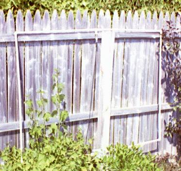